Propagation of uncertainness in SIL confirmation and determination devising
1 Theoretical model
1.1 Reliability theory
1.1.1 Safety instrumented systems
Safety instrumented system provides a protective bed around procedure system by implementing one or more safety instrumented maps which takes the procedure to a safe province. A SIS is composed of any combination of detector ( s ) , logic convergent thinker ( s ) and concluding component ( s ) .
Detectors: it detects the possible or cause of an unwanted incident and bring forthing appropriate electrical signal. The signal is sent to so logic convergent thinker. Examples of detectors can be pressure senders, degree senders, temperature gages, and so on.
Logic Solver: detects the electrical signal transcending a given threshold and sends a signal to the concluding elements. Logic convergent thinkers can be computing machines, programmable electronic accountants ( PLCs ) , and relay circuits.
Final Control Element: It implements the action determined by the logic system. This concluding control component is typically a pneumatically actuated on-off valve operated by solenoid valves.
1.1.2 Safety instrumented maps
ASafety Instrumented Function(Sif) is implemented by a SIS in order to accomplish or keep a safe province. A SIF’s detectors, logic convergent thinker, and concluding elements detects a jeopardy and convey the procedure to a safe province.
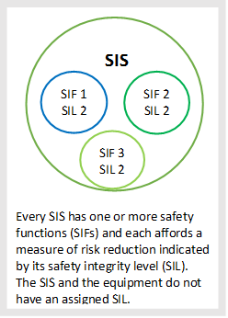
Figure 1: SIS-SIF-SIL relationship
1.1.3 Failure categorization
Failures of SIS elements is classified as unsafe and safe failures, largely. Dangerous failure can be farther split into detected and failures. Detected unsafe failures are those revealed by diagnostic testing, but undetected failures are merely revealed by cogent evidence proving. In sis dependability computation frequently it is assumed that DD failures have a negligible impact on the safety unity ( H. Jin, Lundteigen, and Rausand 2012 ) .
A safe failure does non take the SIF to an insecure province when failed. Failures of SIS elements can be classified as besides into random hardware failures and systematic failures.
- A random hardware failure: occurs at a random clip due to one or more possible debasement in the hardware ( H. Jin, Lundteigen, and Rausand 2012 ) .
- A systematic failure: a systematic failure, besides called functional failure, is related to the design or procedure, operational processs, certification, or other relevant factors. When A systematic failure occurs, the point is still able to run, but does non execute its specified map. The systematic failure can non be easy detected during normal operation or regular cogent evidence testing ( H. Jin, Lundteigen, and Rausand 2012 ) .
1.1.3.1 Common cause failure ( CCF )
A CCF failure causes coincident failure of more than one channel in a multiple channel system in such a manner, which leads to system failure. CCFs may happen due to holding same type of constituents or design lack or unequal care in excess channel, or are located in the same country ( H. Jin, Lundteigen, and Rausand 2012, Lundteigen and Rausand 2007 ) . Several methods exist to depict CCFs in SIS. Beta factor theoretical account is most popular today. ? is the conditional chance of a CCF, when a failure has occurred.
1.1.3.2 Test-independent failures ( TIF )
TIF were introduced as portion of the PDS-method. When a TIF is present, the system will non be as-good-as-new after a proof trial. TIF are those failures which passes the proof trial, but still remain undetected ( H. Jin, Lundteigen, and Rausand 2012 ) .
1.1.3.3 Safety unity demands
The public presentation of the SIS with regard to its assigned safety map is defined in footings of safety unity degrees ( SILs ) . It indicates comparative degree of hazard decrease implemented by safety map.
Four discretedegreesof safety is described in IEC criterion. Each degree represents the step of hazard decrease. Standards require the assignment of a mark SIL for any new or modified SIF within the SIS. All of the SIS design, operation and care picks must be verified against the mark SIL ( IEC 2000 ) . Although a SIL is derived from an appraisal of hazard, it is non a step of hazard. It is the intended dependability of a safety map or system required to accomplish the necessary sum of hazard decrease ( Lane 2004 ) .
A safety map can run low demand manner or high demand manner of operation. Low demand manner is where the frequence of demand for operation of a SIS is non greater than one per twelvemonth and no greater than twice the proof trial frequence ( IEC 2000 ) . In this manner, safety map is operated merely when required to guarantee that the equipment and environment remains in a safe province ( e.g. gas sensing system in boiler room ) .
In instance of high demand manner system, the frequence of demand for operation of a SIS is greater than one time per twelvemonth or greater than twice the proof trial frequence. a unsafe failure of these equipment will take to a jeopardy ( IEC 2000 ) . A simple illustration is a gas concentration measuring by gas sensor system associated with control airing and warming to modulate the concentration of gas in a armored combat vehicle.
Harmonizing to IEC, for these two manners of operation, the safety unity degree of a safety map should be expressed as ( Spellemaeker and Witrant 2007 ) :
- The PFD, the mean Probability of Failure to execute its design map on Demand, in the instance of low demand manner.
The quantitative demand PFD ( Probability of Failure on Demand ) , is related to the chance that the safety map will neglect, when the map is needed. For case, the chance that a SIL 3 safety map will neglect on demand is 0.1 % -0.01 % or in other words, it will work on demand in 99.9 % to 99.99 % instance and associated hazard decrease factor is 1000 to 10000.
- The PFH, the Probability of a unsafe Failure per Hour, in the instance of high demand or uninterrupted manner ( Spellemaeker and Witrant 2007 ) .
Table 1: PFD and RRF ( hazard decrease factor ) for SIL degree every bit defined in IEC 61508 ( Spellemaeker and Witrant 2007 )
|
SIL |
PFD: Low demand manner |
PFH: high demand manner |
Hazard decrease |
|
4 |
? 10-5to & A ; lt ; 10-4 |
? 10-9to & A ; lt ; 10-8 |
10000 – 100000 |
|
3 |
? 10-4to & A ; lt ; 10-3 |
? 10-8to & A ; lt ; 10-7 |
1000-10000 |
|
2 |
? 10-3to & A ; lt ; 10-2 |
? 10-7to & A ; lt ; 10-6 |
100-1000 |
|
1 |
? 10-2to & A ; lt ; 10-1 |
? 10-6to & A ; lt ; 10-5 |
10-100 |
1.1.4 Architectural restraint
For each portion of the SIS, the architectural restraints are expressed by the hardware mistake tolerance ( HFT ) , which once more is determined by the type of the constituents ( type A or B ) , the safe failure fraction ( SFF [ 1 ] ) , and the specified SIL.
1.1.5 Hardware mistake tolerance ( HFT )
The HFT expresses the figure of mistakes that can be tolerated before a SIS is unable to execute the SIF. A HFT of M means that M+1 is the minimal figure of mistakes that could do a loss of the safety map. A KooN architecture tolerates N–K failures ( mistakes ) ; e.g. 2oo3 system tolerates 1 mistake. A hardware mistake tolerance of 1 agencies if there are two devices, the unsafe failure of one constituent or subsystem does non forestall the safety action from happening ( Lundteigen and Rausand 2009 ) .
The 2nd parametric quantity that is used to find the HFT, is the constituent type. IEC 61508 defines them type A and type B constituents. A type constituent is characterized by: ( I ) all failure manners are good defined, ( two ) the behaviour of the constituent under mistake conditions is good known, and ( three ) field informations are reliable and able to corroborate the failure rates that are claimed. B type constituent does non carry through one or more of these standards.
1.1.6 Reliability block diagram
A Reliability Block Diagram ( RBD ) is a graphical illustration of a system which shows the logical connexions of working point that are needed to carry through a specific map. Each constituent in the system is represented by a block. Reliability block diagrams are frequently applied to find the PFD of a SIF.
|
|
|
|
|
a ) |
B ) |


Figure 2: a ) 1oo1 constellation B ) 1oo2 constellation
1.1.7 Impact of proving
There is a nexus between the safety unity and the trial done in the field to verify that the safety map operates as intended. Over clip constituents impetus and the chance to hold failures additions. To maintain the SIL degree at the initial value, it is compulsory to execute a proof trial to look into the handiness of the safety map. Transporting out a proof trial leads to return to the normal state of affairs. There is a nexus between the mean PFD, the trial interval Tp and the average clip to mend. ( Spellemaeker and Witrant 2007 ) . These trials are basically designed to observe random hardware failures.
1.1.7.1 Functional testing
Functional testing is performed manually at defined clip intervals, typically 3, 6 or 12 months intervals.
1.1.7.2 Automatic self-test
In modern system frequently have built in system to observe random hardware failures by automatic self-test. Furthermore, as a portion of self-test the system may find which of the faculties have failed. Butallrandom hardware failures can non be detected automatically, it’ public presentation depends on voting logic and operating doctrine.
1.2 Standards and guidelines
1.2.1 IEC
Assorted international criterions are used to verify conformity with legal demand for organization/system. IEC 61508 and IEC 61511 are used as a benchmark for acceptable good pattern for industry by world-wide Safety regulators for industry. IEC 61508 is concerned with accomplishing functional safety and describes a to the full hazard based attack for finding Safety unity degree demands ( OLF 2004 ) .
For gauging dependability of a SIS, the IEC criterion describes a figure of possible computation attacks including analytical expression, dependability block diagrams, mistake tree analysis, Markov modeling, petri cyberspaces ( Innal 2008 ) . IEC criterion do non mandate one peculiar attack or a peculiar set of expressions, but leave it to the user to take the most appropriate attack for quantifying the dependability of a given system or map ( IEC 2000 ) .
The standard specifies the hazard and steps in the design of safety maps. It provides the functional safety demands covering random hardware failure, systematic failure and common cause failures. IEC 61508 is a generic criterion applicable to several industries. It helps in developing sector criterions ( e.g. machinery, process chemical workss, medical or rail ) or merchandise criterions ( e.g. gas sensing ) ( Spellemaeker and Witrant 2007 )
IEC 61508 and IEC 61511 ushers all necessary activities during the full lifecycle of the systems for thedirection of functional safety. IEC 615081 requires merely random hardware failures to be considered in PFDavg computations, while systematic failures should be managed by a proper safety direction plan. The chief statement for this attack is that systematic failures do non follow the same failure processes as random hardware failures. The standard gives a figure of demands to cut down the systematic failures ( OLF 2004 ) .
1.2.2 OLF 70
This criterion provides a guideline on the footing of IEC 61508 and IEC 61511 for lower limit SIL demands which are based on experience with a intent to derive equal safety degree for crude oil activities in Norway. In comparing to to the full put on the line based position as described in IEC 61508, this criterion will straight concentrate toward hazard designation and designation of divergences from minimal SIL demand. To guarantee a better public presentation degree, stricter SIL demand has been chosen.
OLF describe minimal SIL demand alternatively of to the full hazard based attack as described in IEC 61508 for finding SIL demand. It helps the organisation to avoid clip devouring computations and certification is possible. In instance of divergence from demands harmonizing to this guideline due to technological progresss or particular conceptual or operational facets, IEC 61508/61511 should be followed.
1
